
Part Three - A Typical Case Study: Pump Supplied System
1.General Introduction
The below mentioned bus compartment fire extinguishing system is designed as per GA1264-2015, driven by 24V DC pump. The system is composed by water tank, DC pump, pipelines, nozzles, and control panel (as per fig.1).
In the event of a fire, the driver or passenger manually activates the system, and the fire extinguishing agent stored in the water tank is sprayed to the passenger cabin through the DC water pump, pipeline and nozzle to extinguish the fire. At the same time, after the water pump starts, the buzzer on the control panel will give an alarm, warning passengers and surrounding people to evacuate from the fire scene. After the fire is extinguished, the water pump can be turned off manually, or the liquid level switch can be linked to turn off the water pump after the agent is sprayed (the working principle of the system is shown in Figure 2).
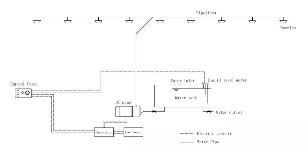
Figure 1
| The Maximum Applicable Object | 12-meter-long bus |
| Nozzle Nos: | 8 |
| Design Spray Intensity | 2.4L/(min m2) |
| Design Spray Time | 2min |
| System Response Time | less than 4s |
| Fire Extinguishing Agent Storage Capacity | 160L |
| Minimum Applicable Temperature | - 5°C |
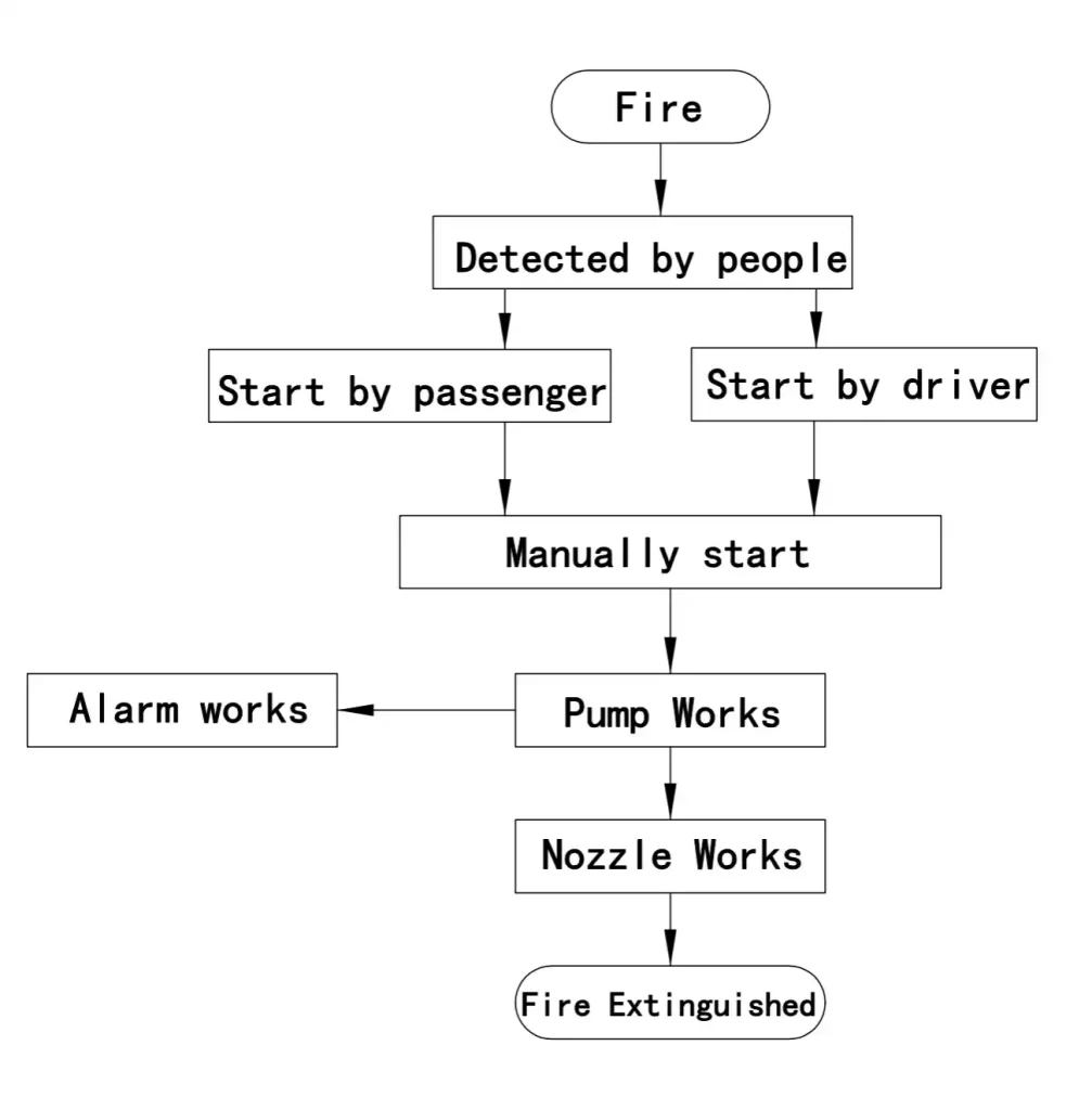
Figure 2
2.Components And Technical Information
2.1 Water Tank
The water tank is located on the upper part of the device, with a size of 540*400*800 (length×width×height), a nominal volume of 173L (as shown in Figure 3), and a fire extinguishing agent storage volume of 160L. The water tank is composed of a box body, a water inlet, a water outlet, a water discharging port, and a liquid level sensor. The water inlet is automatically opened when the external positive pressure or internal negative pressure reaches a certain value. The water inlet end cover is also provided with a positive pressure vent hole. When the vapor pressure of the fire extinguishing agent reaches a certain value, the positive pressure vent hole is opened, thereby ensuring that the internal pressure of the water tank is kept within a safe range. The water outlet is equipped with a filter screen with a mesh number of 20 meshes, and the side length of the mesh that meets the requirements of the specification should not be greater than the requirement of 20% of the diameter of the pump suction inlet. The fire extinguishing agent stored in the water tank is a water-based fire extinguishing agent with a mixing ratio of 6%, which is safe and non-toxic to humans and has no damage to the environment.
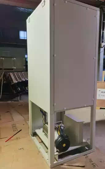
Figure 3
2.2 DC Pump
The DC water pump is composed of a water pump and a DC motor (as shown in Figure 4). This type of motor consists of a motor body and a driver (as shown in Figure 5). It is developed on the basis of a traditional DC motor. Its electromagnetic structure is the same as that of a traditional DC motor, but the armature winding of the brushless DC motor is placed on the stator. , the rotor is a permanent magnet made of permanent magnet material. Permanent magnet brushless DC motors replace the mechanical brushes and commutator with an electronic commutator, eliminating the sliding contact mechanism.
| Pump Flow-Through Parts Material | SS304 |
| Rated Flow Rate | 75L/M |
| Rated Working Pressure | 4.8Bar (0.48MPa) |
| DC Motor | Permanent magnet brushless DC motor |
| Motor Rated Voltage | 24V |
| Motor Rated Power | 1.4KW |
It has the advantages of large starting torque, soft start and soft stop, no sparks, resistance to bumps and vibrations, low noise, reliable operation, high efficiency, maintenance-free, and long service life. The control principle of the permanent magnet brushless DC motor is shown in Figure 6.
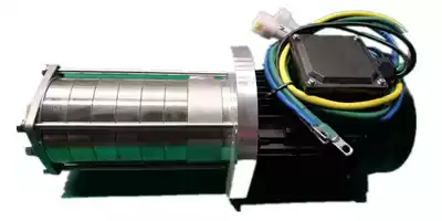
Figure 4 DC Pump
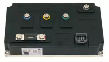
Figure 5 DC pump driver

Figure 6 Control principal
LanZhong designs and produces DC pump for bus compartment fire extinguishing system.

2.3 Pipelines
The system pipeline is made of 304 stainless steel, which can be flexibly connected alternately with hard tubes and hoses according to the layout of the bus roof. The pipeline interface is connected by a live joint with a nominal diameter of DN15 (as shown in Figure 7). After the pipeline is installed, it needs to be sealed with a plug, and the self-distributed air source of the production assembly line is used for purging and pressure testing (as shown in Figure 8) to ensure that the pipeline has no leakage. After the pipeline pressure test is completed, start to close the top interlayer, and continue to seal the nozzle installation port with a plug (as shown in Figure 9), until the vehicle is put into use and the nozzle is replaced.

Figure 7 System Pipelines
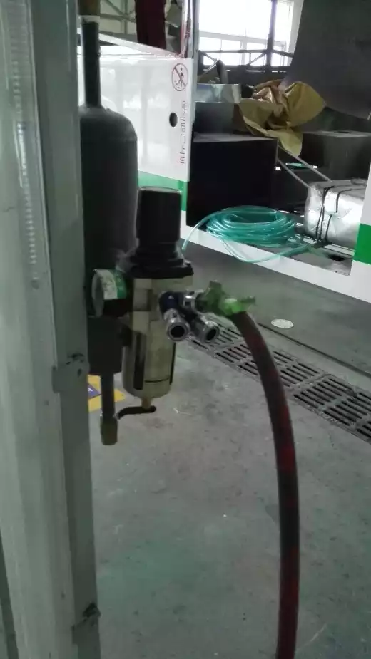
Figure 8 Air Source
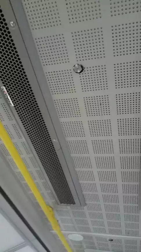
Figure 9 Plug
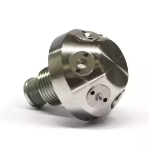
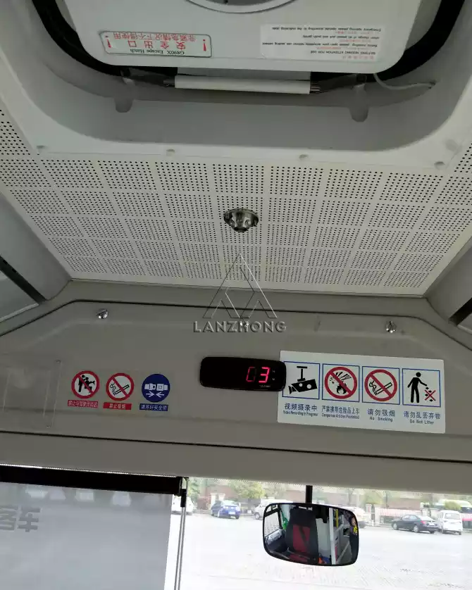
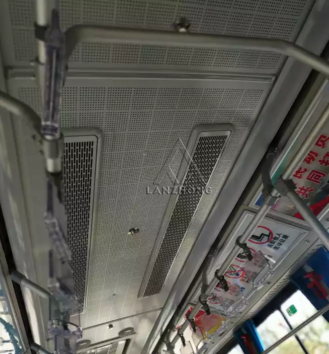
2.4 Nozzles
The nozzle is made of SS304 or SS316 and consists of nozzle body, micro nozzles and filter. . The core components of the water mist nozzle are 6 centrifugal micro nozzles installed on the conical surface of nozzle body, which atomize and spray the extinguishing agent.
| K Factor | 4.5 |
| Min. Working Pressure | 2Bar (0.2MPa) |
| Spray Angle | 150° |
| Working Pressure Of The Nozzle At The Most Unfavorable Point | 4Bar (0.4MPa) |
| Flow Rate @ 4Bar | 9L/M |
| Filter screen filtering area | 295.3mm² |
| Filter screen mesh size | 60 mesh |
3.System Installation ways
There are two types of installation ways on the bus. The most widely applied way is pre-installed during the manufacturing of the bus. And the second way is modification on existing bus.
3.1 Pre-installed during the manufacturing of the bus.

Bus Frame
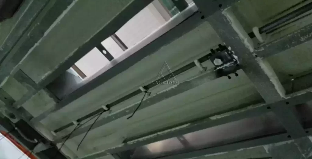
Pipelines to be installed in the frame of the bus
3.2 Modification on existing bus.
Some of the buses are ready made and require modification by adding the low pressure water mist system.

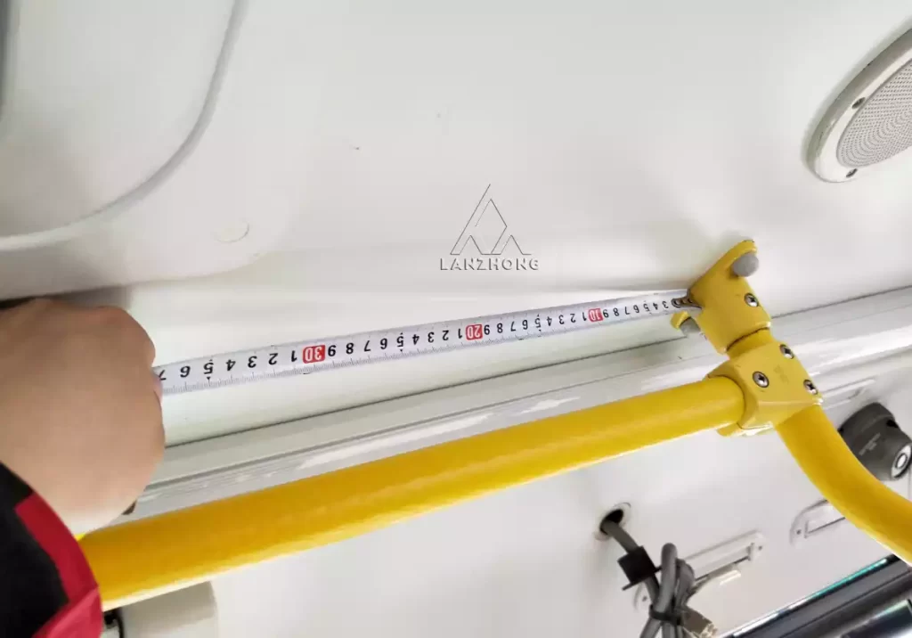
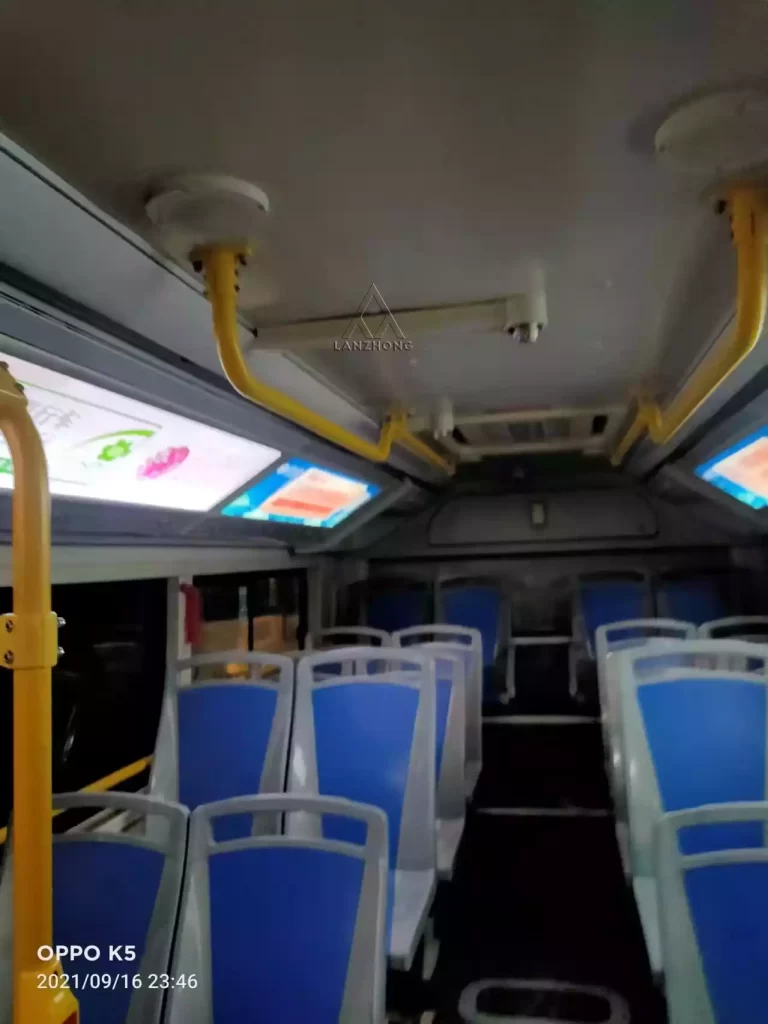
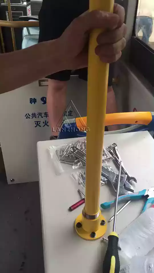
Water pipe, concealed in the bus handrail
LanZhong is professional in water mist nozzle production and also possesses rich experience in all kinds of water mist systems, which allows us to provide the most suitable and highly qualified water mist nozzles.